
One of the things that happens when you live with someone is that you have to make space concessions to them – sure, you can afford a larger overall area, but there are two of you in it, so you can’t just completely take over. So as my wife got selected by her company to go work on a project abroad for a month, I rejoiced that I could finally bring my rPi and assorted bits out of the loft and complete some project 🙂
Turns out, it’s been longer than I thought since I was last poking around on it… I bought it before the London Olympics (when we bought the house), so it’s officially ancient (an old v1 model B pi) and near everything I had planned was based loosely on a project I’d seen more than 6 years ago, that was no longer recorded anywhere. Still… it’ll be fine, I’ll figure it out, right? RIGHT?
First project – build an arcade board. By this I mean a portable bit of kit housing the pi, and the controls that I can take to someone else’s place and beat them at Street Fighter 2 on (the definitive multiplayer game of my childhood). For the Blue Peter version of this build, you would need – one rPi, a bunch of arcade buttons, 2 joysticks, some sort of board, a bunch of resistors, wires and a hat of some kind for your pi (I used a HumblePi, which they probably do not make any more).
I had done some playing around with the pi in the past (an easy few bits of breadboard tinkering, an early raspBMC machine, piCraft… easy afternoon things), but no end to end projects completed. From this I’d bought a couple of I2C chips and messed around with them, but I have not planned to use them on this project – direct GPIO all the way for the arcade controls. Is there a good reason for this? Well, simply that I didn’t think I’d need them for this build – an old rPi B v1 has potentially 17 GPIO pins available if you’re not doing other things with the Pi (beware, some applications can make certain pins unusable, and there are some gotchas with some of the pins that are earmarked for other primary/secondary purposes such as I2C).
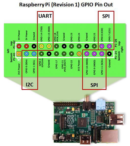
Any of the pins earmarked as something other then power (Ground, 5V, 3.3V) can be used as GPIO if you ensure they are actually marked as GPIO pins – in all pi OSes I have poked around with the I2C pins are not marked as GPIO by default, so they need to be enabled if you want to use them. I’ve seen a mix with the UART pins, sometimes they need enabling to be used as GPIO, sometimes not, depends on how your OS is configured. I’ve not yet seen SPI enabled by default, but it could happen, worth checking if you see issues using those pins. There are a bunch of helper programs to help you with GPIO on the Pi, such as wiringPi and pigpio, but I’ve found just doing it all in config files (to enable the pins as GPIO) and python code (to accept input/output from them) to be easy enough.
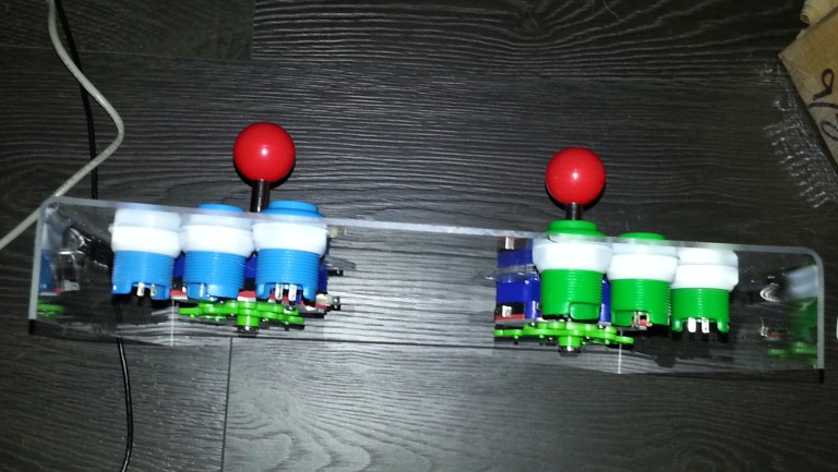
Anyway, on to the build itself. I wanted a two player 3 button setup (because this is the type of arcade machine I remember – badly as it turns out, as most are 2 or 6 buttons). Each button requires one GPIO connection (plus one power/ground) and standard joysticks are essentially 4 buttons (up, down, left, right) – so this setup would require 14 GPIO pins, which would leave up to three for other controls (perhaps start and select would be a good plan). The arcade buttons kit I bought off ebay (in 2012) had about 20 buttons in four colours, and I’d bought two joysticks too. Back then all the options I found had you directly soldering to the control, but more recent builds I’ve seen use a no-soldering approach with crimped wires plugging into pins on the controls – if you have a choice and a crimper, this is a much better plan (easier to change, and less chance of cocking it up).
For the board itself I wanted to use something durable, so I used an A4 sheet of acrylic (3mm thick I believe) – I have few of these I bought to use as small cheap whiteboards. I’ve tried to work a few awkward materials before, and acrylic has always proven itself to be a pain as soon as there’s an unusual shape, so while I wanted the edges bent over to create a cavity under the board for the controller bases, pi and wiring that would have to wait until I’d drilled the holes for everything.
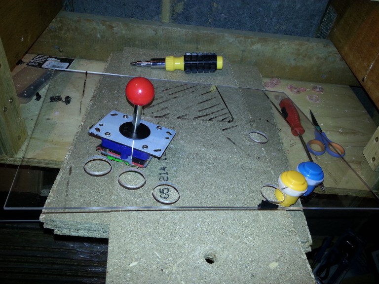
The absolute top tip with acrylic is not to rush anything. For button holes like this, on wood I’d probably drill a centre hole and then just use that to guide and go immediately to the desired size, in acrylic I find it cracks, it moves, the bit won’t always bite, it just generally doesn’t want to play if the hole is over a very small size, so to get to the size I needed I just went super slowly drilling a couple of guides and widening those until they were the width of the centrepiece of my holesaw bit, then doing the main hole as slowly as possible. I was painstaking for the first 6 holes (joystick hole is the same size as the buttons), sadly on number 7 (the penultimate one) I decided to skip one intermediate size on the guide hole and it split the board a little 😦
The board was going to need to stand on it’s own with space underneath for a pi and the bottom of the controls, so I bent the edges down 90 degrees using a heatgun (a really overpowered hairdryer – some people online had used an actual hairdyer for similar acrylic shaping, presumably their hair is now so crispy it is basically ash, because my acrylic sheet was glowing red hot and the hand I was holding the heat gun with required a workman’s glove to protect it from the heat before the sheet began to bend properly over the wooden block I was using for a straight edge).


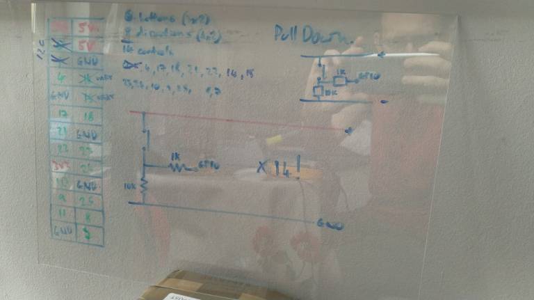
It looked a lot more like an arcade board with all the buttons drilled in… now for some serious wiring. I wasn’t too sure about using the internal pull-up/pull-down resistors in the pi itself, as it’s been nearly 20 years since I studied any electronics and didn’t know if mixed values for the pull-down resistors would cause issues (the I2C pins use 1.8k internal resistors, which I believe is different to the value of the other GPIO pins) – looking back on it this should be no issue, each button is a logically different circuit and anywhere between 1 and 10k would be fine as a pull-up/down, but I didn’t really know or feel the desire to spend time doing the reading before I started wiring, I was a bit excited to get going 🙂
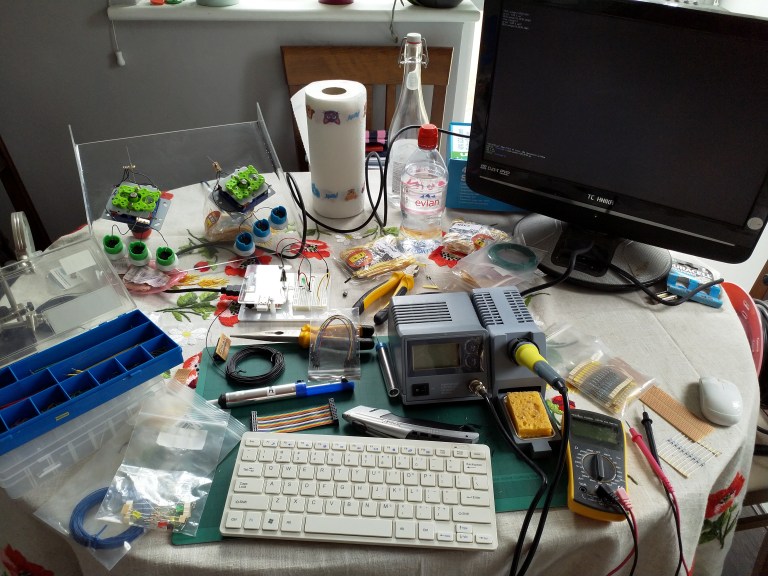
Sadly, Maplins (UK’s Radio Shack equivalent) went into administration recently… for me this meant I got a really nice soldering station for next to no money (replacing one I bought on amazon for less than £10, which after a few uses was tripping the RCD on my home plug socket circuit causing the tamper alarm on my house alarm to go off at intervals every time I used it, so a worthwhile upgrade!), and bought a load of wire and rolls of resistors on the cheap. With the wife out of town my soldering setup moved out of the loft into the living room (she may have a shock when she gets home)
It doesn’t really matter if you go pull-up or pull-down, the circuit diagram looks roughly the same, both ways you have a common ground and power rail for every component, it just changes which side your button and big resistor go, and whether you’re looking to pull the pin high or low on button contact – both ways are roughly equivalent for my purposes (cue someone telling me why I’m wrong) but I must be consistent throughout otherwise it’ll be hellish to figure out what’s going on. There are some conventions in wiring colours – I’m ignoring all of them, because I did a bit with the wrong colour early on and didn’t want to rewire, so just followed it through and stuck with consistency in the project itself.
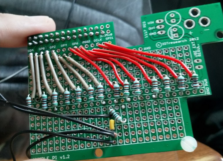
The humble pi has a nice plug-in header for the pi’s pins to go into (on reverse of the pic), it then runs many of these to more convenient locations, and gives you a breakout board almost the size of the pi itself with a power and ground line running through the middle. Each three hole section on the main breakout area is isolated from the others, but connected to themselves. I wish I’d bought a few of these, they were pretty cheap and it’s a good way of keeping many projects separate without buying multiple pi’s (that and multiple SD cards, one per project).
Here I’ve got black for the power lines (I know, shoot me now), yellow wire is a connection between breakout sections, red is one of the players, grey is the other. Coming off the board these transition to blue or green, same as the buttons (yes, it’s all over the place, the reason was that I had a bunch of pre-cut wire suitable for the board and it was red/grey, not blue/green, and I’m a waste not want not guy).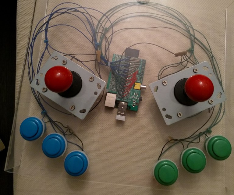
There is some mess on the shared power lines for the buttons and joysticks, and to be honest the wire length wasn’t right in some places, but it’ll do for a first go. There’s about a hundred solders in this, so be aware you could cut it down significantly if you chose to use the internal pull-up/down resistors, and next time I will be reading up on using those, because 4 straight hours of soldering (I’m not well-practised, there was a fair bit of redoing the early ones) was more draining than expected.
Next up, software.
Due to originally conceiving this project 6 years ago, the arcade software I was planning to use (piMAME) is pretty much dead now, and finding the literature I had been planning to use was proving impossible. So sadly, I have had to switch to another software package. There are a bunch to pick from, but most now expect you’ll be using a USB header for your arcade controls (i.e., doing it the easy way like a big chicken, albiet one who will actually finish the project in less than a weekend). If you want the destination and are less fussed about the journey, the USB header (and a decent wire crimper) would have removed pretty much all the soldering and the upcoming GPIO funtimes. As I’m still doing some tinkering software-side I’m going to come back to that in a second blog post.
So far, this has been a fun build, and I’m learning a lot… I also have a list of things I need to learn more about for the next build, and it feels twice as long as what I currently know! This feels like a good time to pause, and puts me in mind of the famous quote by John Archibald Wheeler (a physicist who coined the term “black hole”):
We live on an island surrounded by a sea of ignorance. As our island of knowledge grows, so does the shore of our ignorance
